US$0.00
0

SOLIDWORKS Macro for Automated Batch Export of Configurations to STEP

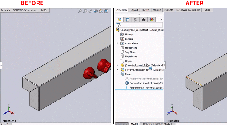
Description The SOLIDWORKS macro provided here is a means to batch export configurations to STEP. System Requirements Pre-requisites Results Steps to Set Up the Macro After the macro has been run, you will then be prompted to input two critical

SOLIDWORKS Macro for Automated Mate Toggling and An image divided into two side-by-side sections labeled "Before" and "After," showing a SOLIDWORKS software interface. The "Before" section displays a 3D model of a rectangular base with two red cylindrical components attached, viewed in an isometric motion study. The feature tree on the left lists "Control Panel" and "Valve Assembly" with constraints like "Angle 0 Deg" and "Concentric." The "After" section shows the same model with an additional red cylindrical component added to the right side, and the feature tree updated to reflect the new assembly and constraints. Both sections include toolbars and a 3D view with axes indicators.

SOLIDWORKS Macro for Automated Mate Toggling and Assembly Constraint Testing

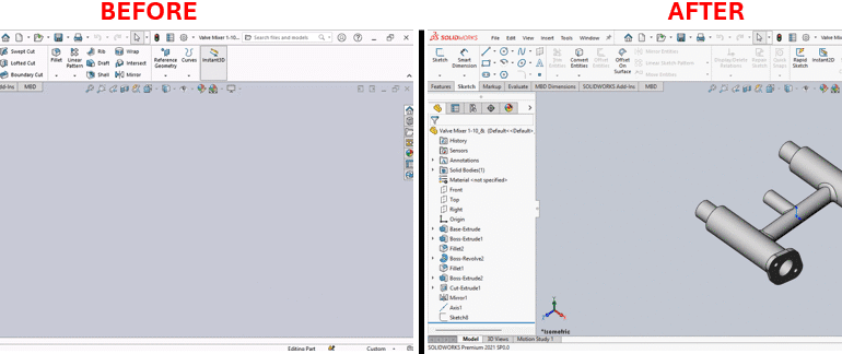
Description System Requirements Pre-Requisites Results Steps to Set Up the Macro VBA Macro Code Macro You can download the macro from here. Need to customize the macro? Contact us today to help create a more powerful, custom solution for your specific

SOLIDWORKS Macro to Create Custom ISO Views and n image divided into two side-by-side sections labeled "Before" and "After," showing a SOLIDWORKS software interface. The "Before" section displays a partially constructed 3D model of a valve with a few extruded components and a feature tree on the left listing steps like "Base Extrude" and "Cut Extrude." The workspace is mostly empty with a gray background. The "After" section shows the completed 3D model of the valve, featuring a more detailed structure with multiple cylindrical and connected parts, and the same feature tree on the left with additional steps like "Fillet" and "Mirror." Both sections include toolbars and menus at the top, with the "After" section highlighting the finalized design in a 3D view.

SOLIDWORKS Macro to Create Custom ISO Views (8 Orientations)

Description System Requirements Pre-requisites Results Steps to Implement the Macro VBA Macro Code Macro You can download the macro from here Need to modify the macro to meet specific requirements? Contact us today to see how our experience can help provide

SOLIDWORKS Macro to Insert Part into New Part Document

SOLIDWORKS Macro to Insert Part into New Part Document (Derived Parts)

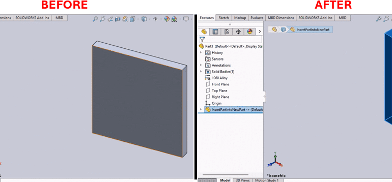
Overview This utility is intended for SOLIDWORKS engineers who are looking to easily create a derived part from an existing design. This SOLIDWORKS macro to insert part into new part document automates this process of opening a new part document

SOLIDWORKS Macro to Toggle Dimension Style and An image divided into two side-by-side sections labeled "Before" and "After," showing a software interface for document properties and units settings. The "Before" section displays a table with basic unit types (e.g., length, angle, mass) and their corresponding units (e.g., millimeters, degrees, grams) set to 12 decimal places, with options for fractions and more. The "After" section shows the same table with updated settings: length is set to "none" with 32 decimal places, dual dimension length is in inches with 12 decimal places, and other units remain the same. Both sections include a search options bar, drafting standards, and additional settings like borders and centerlines, with the "After" section highlighting changes in red.

SOLIDWORKS Macro to Toggle Dimension Style: Fraction vs. Decimal

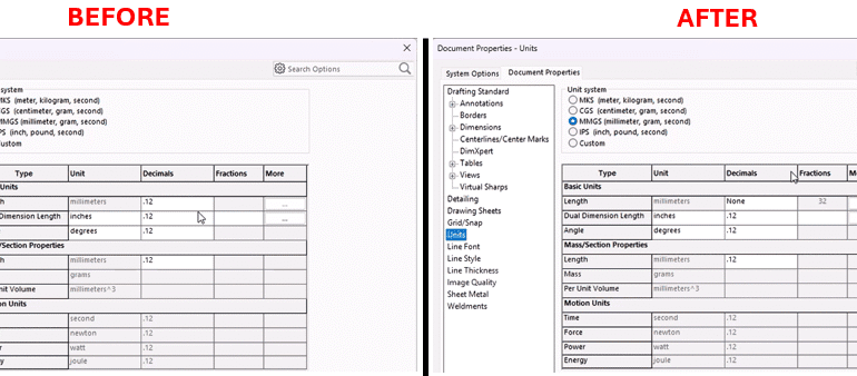
Description This utility is a must-have for SOLIDWORKS engineers who often use both measurement methods. This macro, known as the SOLIDWORKS macro to toggle dimension style, automates the process of toggling the SOLIDWORKS dimension style. The logic is simple but

SOLIDWORKS Macro to Apply Custom Color and Width to Drawing Edges and An image divided into two side-by-side sections labeled "Before" and "After." The "Before" section shows a rectangular frame with five circular targets inside, each with a crosshair, and one target highlighted with a blue outline. The "After" section shows the same rectangular frame with the same five targets, but the highlighted target is now outlined in red, and a yellow cursor icon is positioned near it, indicating a change or selection. Both sections have an orange dashed border around the frame.

SOLIDWORKS Macro to Apply Custom Color and Width to Drawing Edges

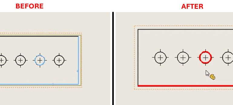
Description This tool gives SOLIDWORKS engineers detailed visual control of their technical documents. The SolidWorks macro to apply custom color and width to drawing edges applies customized line properties (both color and width) to selected SOLIDWORKS drawing edges. This provides

0
    0
    Your Cart
    Your cart is emptyReturn to Shop