US$0.00
0
SOLIDWORKS Macro_ Export Part and Assembly to IGES File and An illustration of a computer screen displaying the SolidWorks logo in red. An orange arrow points from the screen to a 3D model of a mechanical part and an IGES file icon, indicating data export. Surrounding the screen are icons of code brackets and a gear, symbolizing programming and design. A gray 3D cube and a blue mechanical component are also shown, representing 3D modeling. The background is light, suggesting a tech-focused environment.

SOLIDWORKS Macro: Export Part and Assembly to IGES File

Description This SOLIDWORKS macro provides a fast and efficient way to export active documents to the IGES file format (.igs). Designed for SOLIDWORKS parts and assemblies, this macro automatically saves the exported IGES file to the same directory as the

How To Export the Active Document As a STEP File

This macro allows you to export the active document as a STEP file to the same directory as the original file. It will automatically name the STEP file the same as the active document, but with the .step extension. This

How to Measure Sketch Length and Add Custom Property Using VBA Macro and An illustration showing two side-by-side screenshots of a "Summary Information" window from a software, labeled "BEFORE" on the left and "AFTER" on the right. Each window has a table with columns for "Property Name," "Type," "Value / Text Expression," and "Evaluated Value," with an "Edit List" button and options for "OK," "Cancel," and "Help." The "BEFORE" table lists properties like MDL_EngAppId, Revision, Description, and a new property, with values such as dates and numbers. The "AFTER" table includes the same properties plus two new ones, "Number" and "Total Length," with updated values, including 10.751 for Total Length, indicating changes or additions to the data.

How to Measure Sketch Length and Add Custom Property Using VBA Macro?

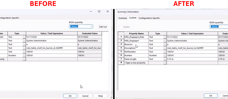
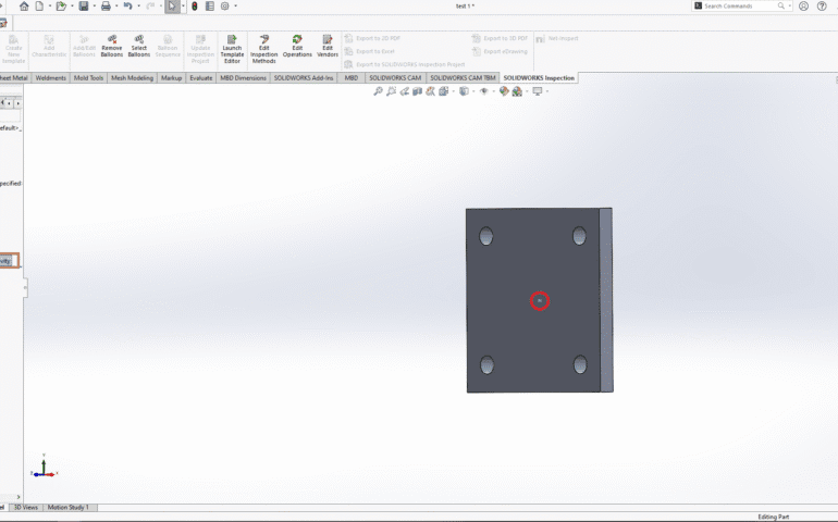
This guide will give you an in-depth idea of a powerful VBA macro for SOLIDWORKS that automates the process to measure sketch length and add custom property using VBA macro. System Requirements Prerequisites Before you run the macro, ensure you

SolidWorks Macro for Creating a Center of Gravity (CoG) Point and An illustration of a person working at a computer, with hands on a keyboard and mouse. The computer screen displays a 3D model of a mechanical part with a hole, viewed in a design software interface showing tools like "Pains," "Origine," "Extrusion," and "Add Step" on the left sidebar. An orange gear icon with a small robot face overlays the screen, symbolizing automation or AI assistance in the design process.

SolidWorks Macro for Creating a Center of Gravity (CoG) Point

This step-by-step tutorial provides an exhaustive tutorial on how to utilize a SolidWorks Macro for creating a center of gravity (CoG) Point in placing a 3D sketch point automatically at the Center of Gravity (CoG) of an assembly or a

Automate the Convert Entities Tool for Inner Loops Only and A screenshot of a SolidWorks CAD software interface displaying a 3D model of a mechanical assembly named "Bracket_Assembly." The central viewport shows an isometric view of a gray L-shaped bracket with a circular hole, mounted on a purple base plate, with a yellow "COM" (Center of Mass) marker at the hole's center. The left sidebar, the FeatureManager Design Tree, lists components and features including "Origin," "Front Plane," "Top Plane," "Right Plane," "Extrude1," "Fillet1," and "Mate1." The top menu bar includes tabs like File, Edit, View, Insert, and Tools, with a status bar at the bottom showing "Edit Assembly" and green X, Y, Z axes indicators.

How Do I Automate the Convert Entities Tool for Inner Loops Only

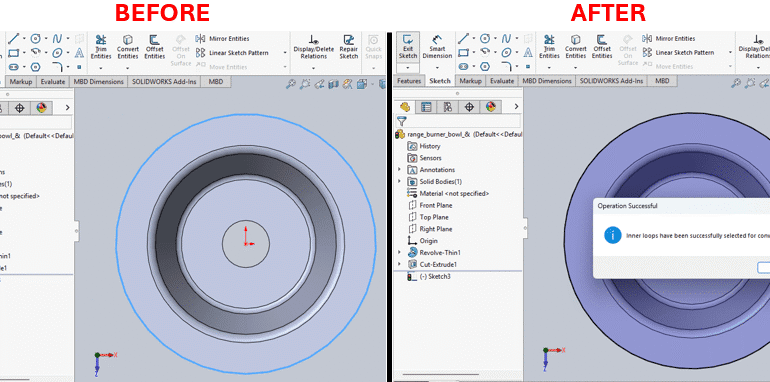
This article is going to show you how to use a simple VBA macro to automate the convert entities tool for inner loops only. This makes the whole sketching process faster and easier. The VBA Macro: One-Click Access to Inner

How Can I Add Center of Mass to A Part in SOLIDWORKS and An illustration of a 3D CAD model showing an L-shaped gray component with a circular hole in the center, where a yellow "COM" (Center of Mass) marker is placed. To the left, a sidebar lists design elements: "History," "Sensors," "Annotations," "Front Plane," "Top Plane," "Right Plane," "Origin," and "COM," with icons next to each. A 3D coordinate system (X, Y, Z axes in green, red, and blue) is visible in the upper right corner, indicating the model's orientation. The interface appears to be from a SolidWorks or similar CAD software.

How Can I Add Center of Mass to A Part in SOLIDWORKS?

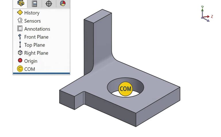
Ever felt the need to add a center of mass point to your SOLIDWORKS part, but don’t know how to? You’re in the right place. In this guide, you’ll learn how to add center of mass to a part in

0
    0
    Your Cart
    Your cart is emptyReturn to Shop